The second part in a series on the history of how we conquered the sound barrier. Written by Dale J Ferrier
Windtunnels and Props
When we think about going supersonic we imagine gleaming jets with swept wings, pointed nose cones, and powerful engines rocketing through the sky at blistering speeds. We don’t usually picture the lumbering wood and canvas machines of the First World War for which many couldn’t go even as fast as some modern cars. But, quite unexpectedly, the sound barrier arose as a challenge to engineers around the final stages of that war. To understand why, we must look not at the entire aircraft which remained far from ever reaching anywhere close to the Speed of Sound, but rather a part of it – namely the propeller.
During WWI, the development of aero engines had tremendously accelerated as each nation sought an edge over its enemies. Long gone were the engines that only just about carried the Wright Flyer into the air – the aeroplanes of the Great War had the power to dance around the heavens at will. But, as the power of these engines grew, larger faster propellers were needed to translate that additional power into thrust and in time a limit began to be reached. The tips of the propellers began reaching the Speed of Sound, and engineers found that when they did, the enormous drag created not only sapped ever greater engine power but also reduced the thrust the propeller could produce.
The spike in drag when the tips reached transonic speeds was not unexpected for this phenomenon was first discovered by British engineer Benjamin Robins during the 18th Century using his ballistic pendulum. Robins was investigating projectiles rather than propellers but by the end of the following century, a great deal was understood about supersonic projectiles such as bullets and artillery. However, unlike munitions whose flight time is very brief, when it came to the propeller problem, engineers wanted to understand how to overcome these effects over a long period.
The effects of transonic flow over propellers became an increasing concern of the British who followed on from Lord Rayleigh’s work in the 19th Century, which through the British Advisory Committee for Aeronautics envisaged grave problems for propellers that neared the Speed of Sound. Experiments by E J H Lynam seemed to confirm the Committee’s fears. A low-pitch propeller driven so that its tips entered the transonic range demonstrated a great increase in drag and a loss of thrust. These demonstrations however did not provide any quantitative data, and further tests with more conventional propellers were proposed.
In taking these tests further, a powerful turbine-driven propeller dynamometer was developed using new thinner wooden designs. When spun up to high speeds, these tests again showed the expected deterioration of the propeller’s performance but provided better data than Lynam’s earlier work. These tests helped to derive the cross-section coefficients of the airfoils and demonstrated that the centre of pressure moved rearwards when reaching the transonic range.
Whilst Lynam used wooden propellers, an aeronautical engineer in the US had been making interesting advances in metal propeller designs. Sylvanus Albert Reed, born April 1854 in New York, began testing his all-metal designs in his attic in 1915 using a 10hp electric motor which turned the propeller up to 19,000rpm. After being made to relocate his testing to the Curtiss Garden City Factory by local police 5 years later, Reed continued to develop his design which included a giant 9-foot propeller fitted to a Curtiss bi-plane.
As part of his research, he drove his propellers to speeds where the tips reached Mach 1.5. Unlike wooden designs, metal propellers could be made much thinner and so when reaching such speeds, Reed observed that they didn’t lose performance, and although he noted a loud penetrating noise they did not produce the same “distressing violence” observed with Lynam’s thicker wooden propellers.
Meanwhile, at the McCook Field, the Americans were beginning their own tests. Unlike their British counterparts, the US team didn’t use spinning propellers but instead looked at driving supersonic flows in a wind tunnel over a stationary airfoil to better assess its behaviour. The problem they had, however, was that there were no wind tunnels capable of achieving such speeds. So, the team at McCook needed to develop one before any experiments could be done.
After some development work, they settled on an Effiel Tower style design which much like how the Parisian tower narrows towards the top, this tunnel narrowed to a 14-inch diameter throat with air being driven into the tunnel by a 200hp engine. Frank W Caldwell and Elisha Fales, who developed the tunnel, measured the flow inside the throat to be the equivalent of Mach 0.64. Despite being far below the Speed of Sound, this proved sufficient to observe the compressibility issues that arise at transonic speeds.
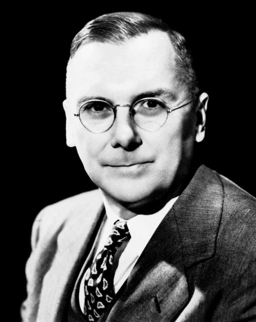
The engineers at McCook knew that they had to push onward to the next step of achieving transonic speeds. Their tunnel had proved useful but the lengthy and expensive redevelopment work required to achieve these higher flows would be prohibitive. So, Hugh L Dryden and Lyman J Briggs who were heading up these next steps, needed to look elsewhere and found their solution in a large 5,000hp compressor which could provide a high-speed jet of air of up to Mach 0.95 down a 12-inch throat. However because the development of the compressor was not yet complete, the pair had to conduct their tests at the General Electric facility in Massachusetts on Christmas Day 1923.
They were quite satisfied with these early tests and later that night ventured out onto the streets to talk over their day’s work. The pair soon noticed that they were receiving many odd looks from passersby. The mystery was soon solved when they figured out that they were essentially yelling at each other after being temporarily deafened from working so near the open high-speed jet – which unsurprisingly made considerable noise.
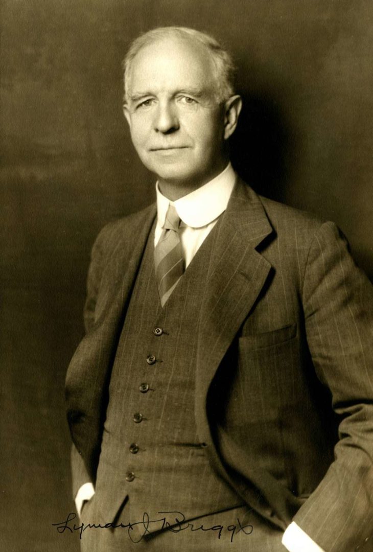
The Christmas Day tests were more a proof concept and provided little in the way of quantitative data, but they did help show the relationship between the Critical Speed and the Low-Speed Velocity distribution along the airfoil, which became a major cornerstone of research in the 1930s. The pair decided to take their research further and obtain load distribution data, but the GE compressor was no longer available. They sourced another but with a 2-inch throat. This new jet provided a flow of Mach 1.08 allowing for the first truly supersonic testing to be done in the US.
It was during these tests that the thin layer of anti-corrosion oil coating the airfoils showed that the flow suddenly separated from the upper surface at a position that became known as the Burble Point – the point of greatest compressibility. Along with the flow separation, the tests also showed that the pressure at the trailing edge shifted from being less than the flow pressure to being greater than it. A phenomenon rediscovered 35 years later by Gadd and Holder in the UK, seemingly unaware of the tests done by Dryden and Briggs. The coefficient of drag was found to peak between Mach 0.95 and 1.08, and for the first time in history, a shock wave was observed standing about half an inch ahead of the leading edge. Observations through Schlieren photography, developed by German physicist August Toepler, allowed for the imaging of fluid flows, especially in regards to the supersonic, and is still in use today.
In 1928, John Stack working with Eastman N Jacobs would help carry on the work of Dryden and Briggs by developing new and better high-speed wind tunnels. The pair managed to rectify the violent flow oscillations that made testing difficult and confirmed the earlier work by Dryden and Briggs in their own airfoil tests. Exact details varied as Constriction Effects were not yet understood. The work by Stack and Jacobs attracted the attention of interesting figures from aviation’s early years. The acclaimed British theorist G I Taylor helped assess the pair’s test data, and one day they were graced with Amelia Earhart who came to observe a test. On that day, she wore a racoon fur coat and when she leaned in to feel the airflow going into the bell of the wind tunnel she got more than she bargained for when the coat was torn from her and ingested into the tunnel.
Work continued until 1930 when the research program ended, but the work done made a significant impact on aircraft design. When Dryden and Briggs were making their early supersonic experiments, aircraft could scarcely achieve over 200mph, but by the end of the decade, 500mph had become a very distinct possibility thanks in part to the work in developing better propellers that could be mounted to ever more powerful engines. A 1924 French report envisioned that by 1930, aircraft could be capable of Mach 0.8, powered by some yet unknown method of propulsion.
These wind tunnel tests also seemed to have played a part in defining the types of sonic flow described in the first section. When the flow was between Mach 0.75 and 1.25, the shockwaves formed by the airfoil reflected off of the tunnel sides and made accurate measurements difficult. But when the flow exceeded Mach 1.25, the angle of the shock wave meant that any reflections were far aft of the test area. As you may recall, speeds between Mach 0.75 and 1.25 is considered Transonic, and above Supersonic.
The great difficulty for aero engineers is not supersonic flight itself, but rather the turbulent and foreboding transonic range that must be surpassed to get there – it appears that wind tunnel testing met the same challenges.
End of Part II

